[Contents] [Intro] [Reference] [Tutorial] [Questions [New [Index]
Overview -> Reference -> Term Representation for Graphs

daVinci Term Representation

daVinci graphs are given in a format called term representation which is composed of plain text ASCII characters. Graphs can be created very easily, even with a usual text editor. But in most cases graphs are automatically generated by an application program, for example with the interactive graph editor application which is part of each daVinci distribution. All kinds of directed graphs can be specified with a term representation: acyclic and cyclic structures or even graphs with multi-edges (i.e. more than one edge between two nodes) and self-edges (i.e. edges where the parent and child node are the same). The term representation of a graph is either loaded from file with menu File/Open... or sent to the API.

Structure of Term Representation

In general, a term is a structure where a superterm (parent) encloses its subterms (children), e.g. parent[child1,child2,child3]. Brackets [...] are used to get a list of comma-separated elements of the same type. This scheme of expressing parent-child relationships can be applied recursively, so each child may have its own children, and so on. Such a notation allows to represent arbitrary tree structures.

To specify graphs, a mechanism of identifiers (called labels in former releases) and references is used in daVinci. For example, if a child node has more than one parent node, then in the term representation the corresponding subgraph of the child appears in only one of the parents as a subterm. This subterm is marked with an identifier (in fact, all nodes and edges need to be marked with a unique identifier). All the other parents of the same child do not duplicate the subterm. Instead, they point to the child by using a reference to the identifier. Note that this way it is even possible to describe cyclic graphs. When loading a term representation, daVinci will construct an internal graph by resolving these references. The linear order of a node's subterm (where the identifier is declared) and a reference to this node (where the identifier is used) is arbitrary in a term representation, so references can be used before the corresponding identifier and subterm appears in the term representation.

Note: You have to make sure that each node and edge in a term representation has its own unique identifier, i.e. do not use the same ID for two objects. In multi-graph mode, each context (graph) has its own scope, so there is no need to have unique identifiers for the union of all current contexts.

Beside the identifier (a unique string) and the list of child nodes (which is probably empty), each node also has a type and a list of attributes which are responsible for the image of a node in the visualization. Types and attributes are discussed below. Between a parent and the corresponding child node, there is an edge in the term representation which also has its unique edge identifier, type and attributes. So, in fact the children of a node are edges and each edge has one node or reference as subterm.

Note: In previous V1.x releases of daVinci, identifiers (labels) for nodes and edges were recommended, but optional. In daVinci V2.x, identifiers are now mandatory to support several new features. For example, identifiers will be sent back to a connected application when the user selects nodes or edges.

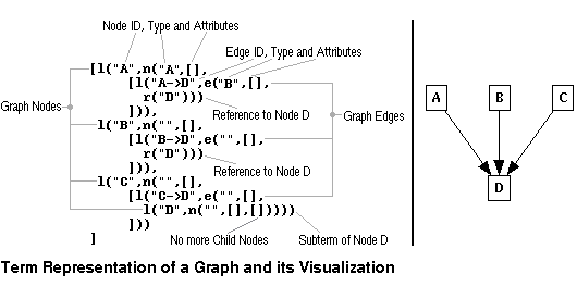
The syntax of the term representation (startsymbol is graphterm) can be found in the API definition. When a graph is loaded from file, whitespace (blanks, tabs or returns) may occur at any position in a term representation. Of course, in strings whitespace is significant. When a graph is sent in term representations to the API, whitespace should be avoided and returns are forbidden. The following figure illustrates a term representation of a small graph and the corresponding visualization in daVinci. A more complex example is demonstrated below.

Multi-Edges and Self-Edges

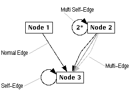
Multi-edges and self-edges are special kinds of edges that are treated in a different way in the graph layout. Multi-edges are present when there are two or more edges between the same parent and child node. All these edges form one multi-edge. The single edges of a multi-edge are spreaded in the middle between the parent and the child (see figure below), whereby the used gap can be adjusted with the
Options/Layout Dimensions... dialog window.

Self-edges are edges where the parent and child node are the same, i.e. a node that has an edge pointing to itself. Self-edges are visualized with a circular edge at the left resp. lower side of the node. The user can adjust the radius of self-edges with the Options/Layout Dimensions... dialog window. Multi self-edges are also possible when a node uses edges with a reference to itself many times in its list of children. These edges are visualized by writing the number of self-edges in the middle of the circle. The attributes of self-edges are considered for the graph visualization (only in daVinci V2.0.2 or higher), but it is undefined which self-edge of a multi self-edge is taken for the attributes. So for example, if you have a multi self-edge containing a red and a blue self-edge, then it is not defined whether the multi self-edge is drawn in red or blue.

The following figure illustrates the visualization of multi- and self-edges in daVinci.

Node and Edge Types

In a term representation, all nodes and edges have a type which is an arbitrary string. The type assigns nodes and edges to classes. It is the intention to define the visualization of all classes in a central file called visualization definition. Node and Edge Types are first used in daVinci V2.1, but the visualization of the classes can only be defined via API commands of
category Visual. For example, it is possible to specify a rule to draw all nodes of some class X with a red circle, instead of using attributes for each individual node of the class. The modification of a rule will affect all elements of the class at the same time. So, the central visualization definition is a comfortable method to define a universal visualization for a family of graphs.

Note: With the command-line option -init you can supply API commands at startup of daVinci. If you put your definitions into such an initial file, you will be able to use visualization defintions without the API. Unfortunately, you will not be able to change the definitions at runtime.

In one of the next daVinci releases, the user will be able to load a file of rules (visualization definition) that defines the visual appearance of a class.

Attributes

Attributes are used in the term representation to specify the visualization of individual nodes and edges. Each node and edge has its own attributes which is a list of string pairs with a constructor a followed by an attribute name and attribute value in parentheses or a constructor m followed by a list of menus. Here is an example for the attributes of a node:
    [a("OBJECT","hello"),a("COLOR","red"),a("FONTFAMILY","times"),
     m([menu_entry("MenuID","Menu Entry")])
    ]
If a particular attribute is specified for a node or edge, it will overwrite the default value for this attribute which is used otherwise. Please look at the paragraph visualization defintion of the concepts document to find out more about the evaluation order for attributes. Node and edge attributes are distinguished from eachother. For example, there are different attributes (more precisely: attribute names) to set the color of nodes ("COLOR") and edges ("EDGECOLOR"). Edge attributes cannot be used for nodes and vice versa. Unknown attribute names and values are simply ignored without any warning. This way, the term representation is both up- and backward compatible with previous and future releases of daVinci. Some attributes, starting with character '_', are needed for internal purposes, but can also be used in a term representation. The usage of attributes is demonstrated in the example below.

Supported Node Attributes

Node Attribute "OBJECT"

This is the most important attribute for a graph visualization, used to specify the text that appears inside a node. Usually, each node should have this attribute. The text, i.e. the attribute value, may be an arbitrary string, whereby international characters are supported (ISO 8bit). The extension of a node in the graph visualization will automatically follow the size of the text by considering the current font, so nodes may have any size. Even multi-line text is supported by using a '\n' inside the attribute value. The default value for this attribute is the empty string "".

Node Attribute "FONTFAMILY" and "FONTSTYLE"

These two attributes are used to visualize the text of a node in a different font. Supported values of attribute "FONTFAMILY" are: "lucida" (default), "times", "helvetica", and "courier". Values of attribute "FONTSTYLE" are: "normal", "bold" (default), "italic", and "bold_italic". For a node, both font attributes do not need to be used pairwise at the same time.

Node Attribute "COLOR"

Can be used to define the background color of a node. The value of this attribute may be any X-Window colorname (see file lib/rgb.txt in your X11 directory) or any RGB color specification in a format like "#0f331e", where 0f is the hexadecimal value for the red part of the color, 33 is the green part and 1e is the blue. Hence, a pallet of 16.7 million colors is supported. The default color for nodes is "white".

Node Attribute "CCOLOR"

Same as attribute "COLOR" but this color is used, if the subgraph of the node is hidden. The default value for this attribute is the value of the attribute "COLOR" or its default value.

Node Attribute "_GO" (Graphical Object)

This attribute specifies the geometrical object used to draw a node. Nine different objects are currently implemented: "box" (default), "circle", "ellipse", "rhombus", "triangle", "text", "invisible", "icon" and "scissors".

Graphical object "text" can be used to simulate edge labels which are currently not available in daVinci. "text" is very similar to object "box", in fact it is a box without the black border. An example graph with simulated edge labels is file example_graphs/edge_labels.daVinci of the daVinci distribution. The trick with simulated edge lables is to use a regular node with graphical object "text" to show an edge label.

With object "icon", a user can define to use a monochrome image for a node in the visualization. Unfortunately, "icon" is more complicated than the other graphical objects. The bitmap file with the image of the icon need to be specified with a second attribute "ICONFILE" (see below), so for icons you need two attributes: "_GO" and "ICONFILE".

Note: The geometrical object "scissors" is normally used to display nodes with hidden subgraphs. So it is not recommended to use this object, because the user may get confused.

Node Attribute "_CGO" (Graphical Object)

Same as attribute "_GO" but this geometrical object is used, if the subgraph of the node is hidden. The default value for this attribute is "scissors". You also need the attribute "CICONFILE", if you choose the geometrical object "icon" as the attribute value, as described for "_GO".

Node Attribute "ICONFILE"

This is used as a supplement for attribute
"_GO" when its value is set to "icon". Attribute "ICONFILE" specifies the (relative) filename of the bitmap used to draw the node as icon. The file must be in X-Window bitmap format (.xbm). Absolute filenames are not allowed as a value for this attribute. daVinci is looking for the file in all directories given by environment variable $DAVINCI_ICONDIR. So for example, when the bitmap of an icon is in file /home/me/images/my_image.xbm, then add /home/me/images to the search path of environement variable $DAVINCI_ICONDIR before starting daVinci, set attribute "_GO" to "icon" and attribute "ICONFILE" to "my_image.xbm" for a particular node. The default value for this attribute is "".

Notes about attribute "ICONFILE":

Node Attribute "CICONFILE"

Same as attribute "ICONFILE" but this file is used, if the subgraph of the node is hidden. The default value for this attribute is "". This is used as a supplement for attribute
"_CGO" when its value is set to "icon".

Node Attribute "HIDDEN"

Attribute "HIDDEN" is used to hide the subgraph of a node initially. This is the same operation available in menu
Abstraction/Hide Subgraph. Supported values for this attribute are "true" and "false" ("false" is the default).

Node Attribute "BORDER"

This attribute defines the border of the geometrical object (see attribute
"_GO"). The values of this attribute may be: "none", "single" (default) and "double". The following geometrical objects support all values: "box", "circle", "ellipse" "rhombus", and "triangle". Objects "icon" and "scissors" can't have "double" borders and objects "text" and "invisible" have no border at all. The default value is "single" to have a normal border.

Node Menu Attribute

This attribute defines the popup menu of a node. This is done with a different syntax than for all the other node attributes. Instead of a(...,...), menus are defined with m(
menus). The popup menu is displayed, if the user presses button BMenu over the node. This attribute is only usefull, if an application is connected. Please have a look at the description in the command category Application Menu for a further description of the parameter menus.

Supported Edge Attributes

Edge Attribute "EDGECOLOR"

In the same way as nodes, the color of an edge can be specified using this attribute. The value of this attribute may be any X-Window colorname (see file lib/rgb.txt in your X11 directory) or any RGB color specification in a format like "#0f331e", where 0f is the hexadecimal value for the red part of the color, 33 is the green part and 1e is the blue. Hence, a pallet of 16.7 million colors is supported. The default color for edges is "black".

Edge Attribute "EDGEPATTERN"

The pattern style of an edge is defined by this attribute. Possible values are: "solid" (default), "dotted", "dashed", "thick", and "double". Note: Thick edges should be used carefully because users might confuse with selected solid edges (both are drawn with the same line thickness!).

Edge Attribute "_DIR"

This attribute is used to control the arrow of an edge. In a graph visualization, each edge usually has an arrow pointing to the child node. This attribute can be used to let the arrow be drawn inverse (i.e. pointing to the parent), to get an arrow at both sides of an edge or to suppress arrows for a particular edge. The supported attribute values are: "normal" (default), "inverse", "both", and "none".

Edge Attribute "HEAD"

daVinci will draw a little image at no, one or both ends of an edge. This behaviour is controlled with the attribute
"_DIR". With the attribute "HEAD" you can define which image this should be. Normally it's an arrow, therefore we talk about arrows in the rest of the documentation. The possible values are: "farrow" (default), "arrow", "fcircle", and "circle", where a leading 'f' means filled.

Edge Menu Attribute

This attribute defines the popup menu of an edge. This is done with a different syntax than for all the other edge attributes. Instead of a(...,...), menus are defined with m(
menus). The popup menu is displayed, if the user presses button BMenu over the edge. This attribute is only usefull, if an application is connected. Please have a look at the description in the command category Application Menu for a further description of the parameter menus.

Example of a Term Representation

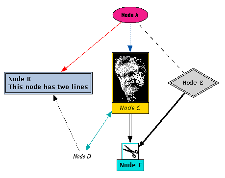
This example demonstrates a complex term representation of a graph, where nearly all available node and edge attributes are used. The figure below shows the resulting graph visualization in daVinci V2.1.x.
 [
 l("Node A",n("Module",[a("COLOR","#f31d8b"),
 			a("OBJECT","Node A"),
 			a("_GO","ellipse"),
 			a("FONTFAMILY","helvetica")],
    [
    l("Edge A->B",e("",[a("EDGECOLOR","red")],
     l("Node B",n("anything",[a("COLOR","light steel blue"),
     			      a("BORDER","double"),
     			      a("OBJECT","Node B\nThis node has two lines")],
        [
        l("Edge B->D",e("",[a("EDGEPATTERN","dotted"),
        	       a("_DIR","inverse")],
         r("Node D")))
        ])))),
    l("Edge A->C",e("",[a("EDGEPATTERN","dotted"),
    			a("EDGECOLOR","#0054aa")],
     l("Node C",n("anything",[a("_GO","icon"),
     			      a("ICONFILE","bkb.xbm"),
     			      a("COLOR","gold"),
     			      a("OBJECT","Node C"),
     			      a("FONTSTYLE","italic")],
        [
        l("Edge C->D",e("anything",[a("EDGECOLOR","#00aaaa"),
        			   a("_DIR","both")],
         l("Node D",n("Module",[a("OBJECT","Node D"),
         			a("_GO","text"),
         			a("FONTFAMILY","times"),
         			a("FONTSTYLE","italic")],[])))),
        l("Edge C->F",e("anything",[a("EDGEPATTERN","double")],
         r("Node F")))
        ])))),
    l("Edge A->E",e("",[a("EDGEPATTERN","dashed"),
    			a("_DIR","none")],
     l("Node E",n("anything",[a("COLOR","LightGray"),
     			      a("FONTFAMILY","courier"),
     			      a("FONTSTYLE","normal"),
     			      a("BORDER","double"),
     			      a("OBJECT","Node E"),
     			      a("_GO","rhombus")],
        [
        l("Edge E->F",e("anything",[a("EDGEPATTERN","thick")],
         l("Node F",n("anything",[a("COLOR","#00dddd"),
         			  a("OBJECT","Node F"),
         			  a("HIDDEN","true")],
            [
            l("Edge F->G",e("anything",[],
             l("Node G",n("anything",[a("OBJECT","Node G")],[]))))
            ]))))
        ]))))
    ]))
 ]
Here is the visualization of this term representation:

daVinci V2.1 Online Documentation - Page update: June 15, 1998